Motor Wiring Diagram Explained
Ac80, ac90, ac100 single phase motors; To understand the power wheels wiring diagram, first, you must.

draw labelled diagram of electric motor explain principle
But if we want to turn this amazing scientific discovery into a more practical bit of technology to power our electric.

Motor wiring diagram explained. In the united states, for low voltage motors (below 600v), you can expect either 230v or 460v. Wiring diagram book a1 15 b1 b2 16 18 b3 a2 b1 b3 15 supply voltage 16 18 l m h 2 levels b2 l1 f u 1 460 v f u 2 l2 l3 gnd h1 h3 h2 h4 f u 3 x1a f u 4 f u 5 x2a r power on optional x1 x2115 v. A wiring diagram may include the wirings of a vehicle.
In a prior post, i go into 10 amazing pieces of advice for how to do your wiring right. 4 wire reversible psc motor; Motor connection diagrams electric motor wire marking & connections for specific leeson motor connections go to their website and input the leeson catalog # in the review box, you will find connection data, dimensions, name plate data, etc.
Just an idea on how a starter motor is wired up and how to bench test itmy other channel shed floor build: A universal electric motor is designed to operate on either alternating current or direct current (ac/dc). For example, how the horns are powered and connected to the controller on your steering wheel.
Make sure that the voltage you will be. Ac80, ac90, ac100 single phase motors; Wondering how a capacitor can be used to start a single phase motor.
The first step is to figure out the voltage of your phases. The first element is emblem that indicate electrical component from the circuit. Some models may have a controller/esc/switch, which is also included in the wiring diagram.
30/03/2017 · detailed examination of a typical motorbike wiring diagram.aimed at the motorcycle owner who needs to read and understand his wiring diagram to aid with elec. Ac65, ac80, ac90, ac100 three phase motors; 4 wire reversible psc motor with a triple pole double throw switch;
The power wheels wiring diagram includes batteries, motors, switches, throttle, relays, and all the wires of power wheels. In this wiring setup, there are 4 windings in series between any two line leads. Draw a diagram to map out your wires and connections.
Please use the updated lecture at: Each component should be placed and connected with other parts in particular manner. Three phase motor connection schematic, power and control wiring installation diagrams.
Especially if you have a kickstarter, things can get really simple, really fast (i.e motorcycle wiring simplified). How an electric motor works—in theory. Toggle switch m1 m1 motor l1 l2 illustration showing components:
Rv electronics work on two types of electrical systems that include alternating current (ac) and direct current (dc). The power wheels wiring diagram helps you to understand each wire and its operation. Draw the necessary wire connections to build the circuit shown in this ladder diagram:
Always refer to your thermostat or equipment installation guides to verify proper wiring. The electrons quickly move to and fro. It is provided with a field winding on the stator which is connected in series with a commutating winding on the rotor.
They show the relative location of the components. They show the relative location of the components. You can actually wire things up from scratch in about half an hour and be ready to give the bike a kick and listen.
3 wire, 3 phase motor; Ac controls a normal control phase of current like a home. Wiring diagrams, sometimes called “ main ” or “ construction ” diagrams, show the actual connection points for the wires to the components and terminals of the controller.
The original wiring diagram showed the proper arrangement of windings to create a larger wye system in which there are four equal windings between any two leads. As 183 wiring diagram with switch. It is substituting flow in light of the fact that the flow of the power isn’t unidirectional.
That being said, there is a wide range of different motors and what you have on hand can be completely different. Ac motor diagrams basic stator and rotor operation an ac motor converts electric energy into mechanical energy. Relay motor toggle switch (spdt) l1 l2 (dashed lines represent connections between relay terminals and socket screw lugs, hidden from sight)
Motor 3ct to 120 v separate control * ot is a switch that opens when an overtemperature condition exists (type mfo and mgo only) t1 t3 motor 3 2 l2 t2. If not, the structure will not. Higginbotham on saturday, february 9th, 2019 in category wiring diagram.
They can be used as a guide when wiring the controller. It is a series wound motor.
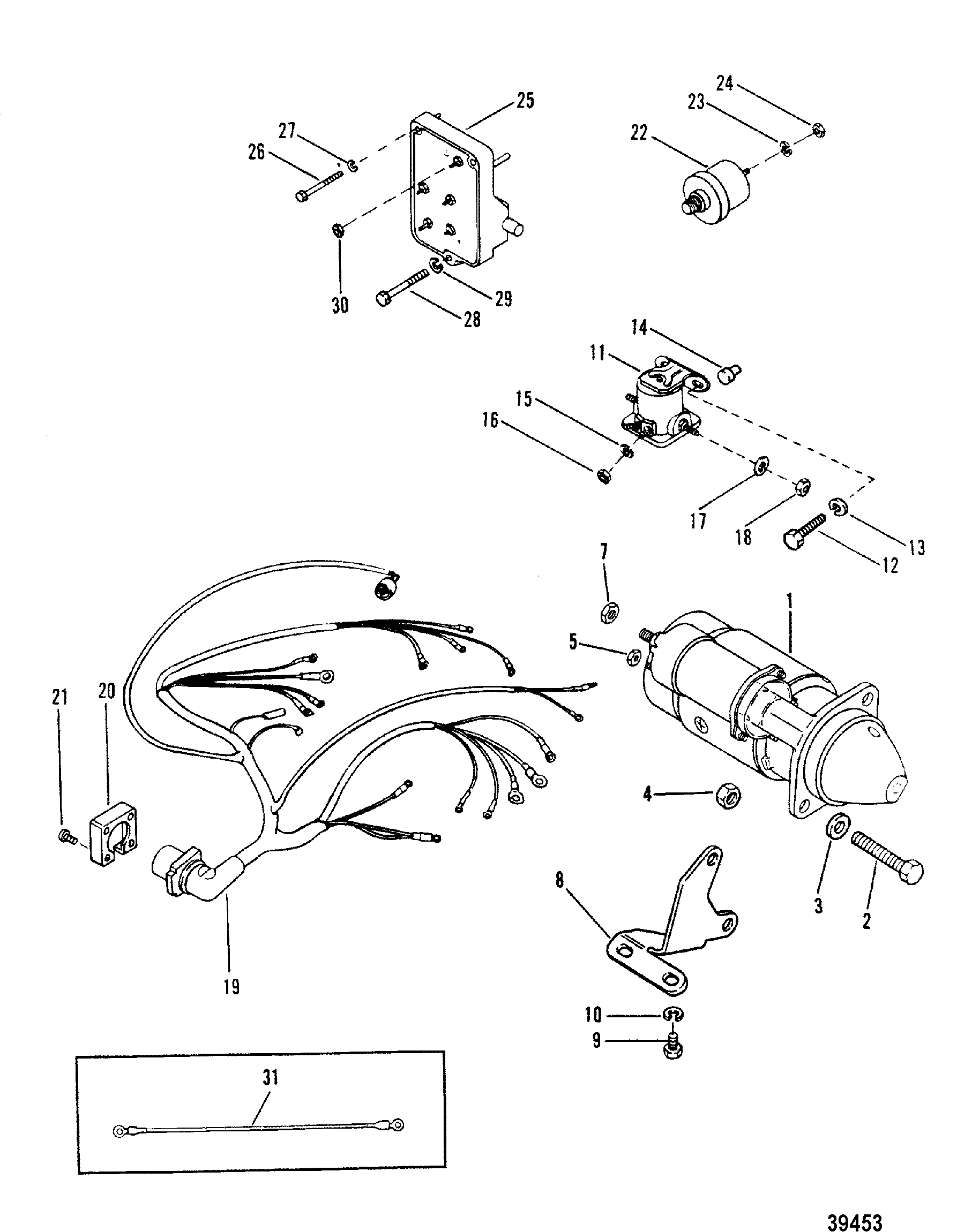
Starter Motor Wiring Diagram Wiring Diagram

Single phase Motor Wiring And Controlling Using Circuit

Car Wiring Diagrams Explained Wiring Diagram And
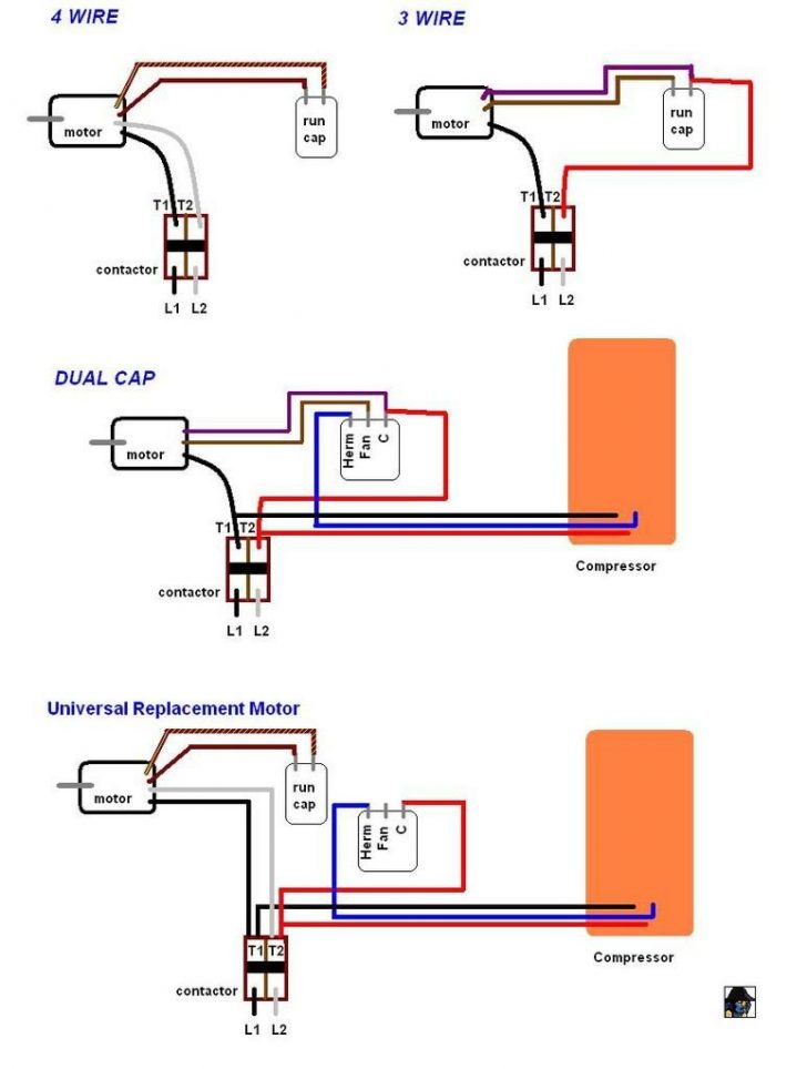
Motor Run Capacitor Wiring Diagram Wiring Diagram
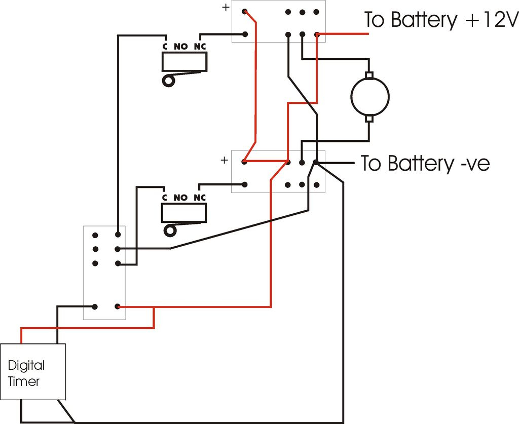
Furnace Blower Relay Diagram Wiring Diagram Explained
Stardelta Wiring Diagram Explanation GRAMWIR

1 Phase Fan Motor Wiring Diagram Wiring View And
Slo Syn Stepper Motor Wiring Diagram / 13 5 Stepper Motors
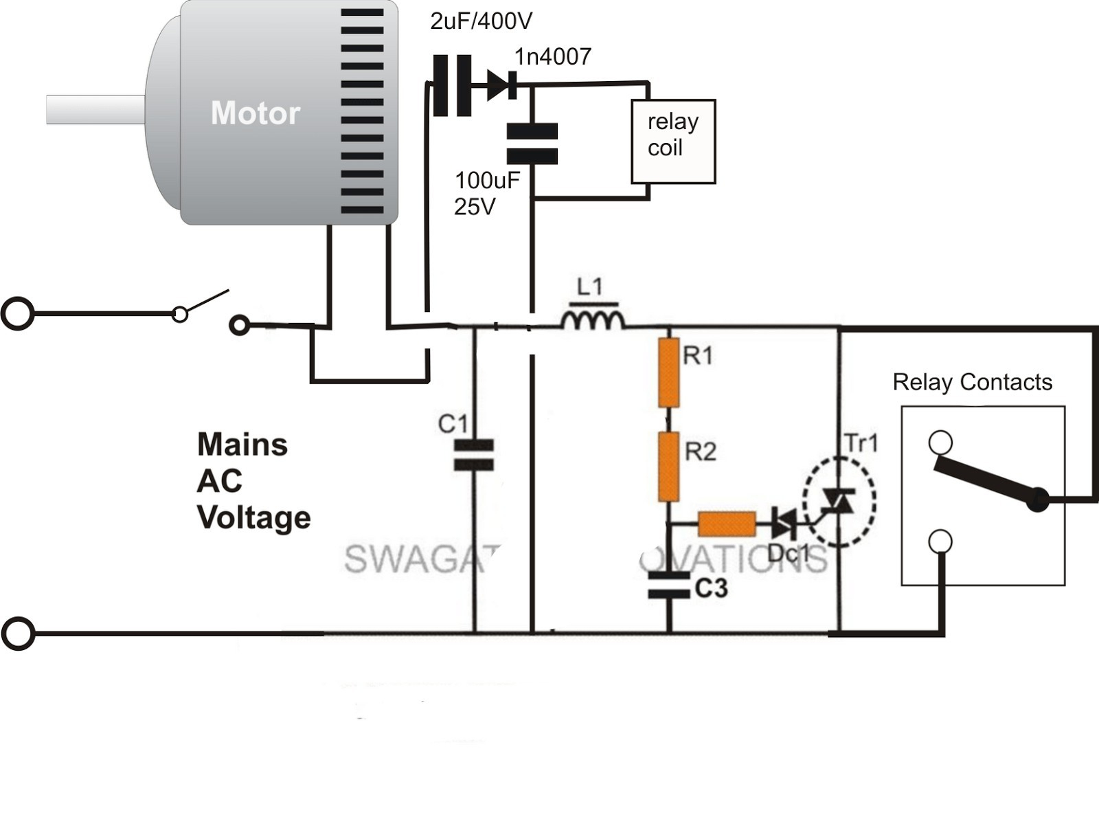
Goodman Run Capacitor Wiring Diagram Wiring Diagram
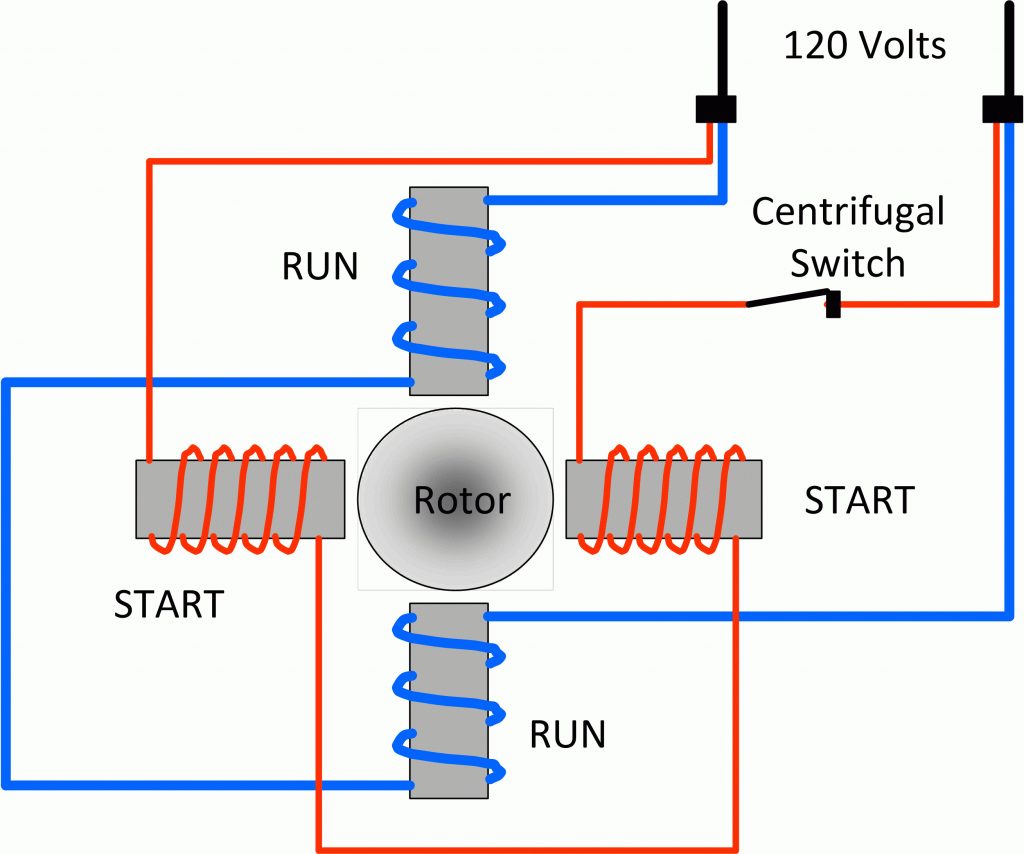
Wiring Diagram Single Phase Electric Motor Wiring
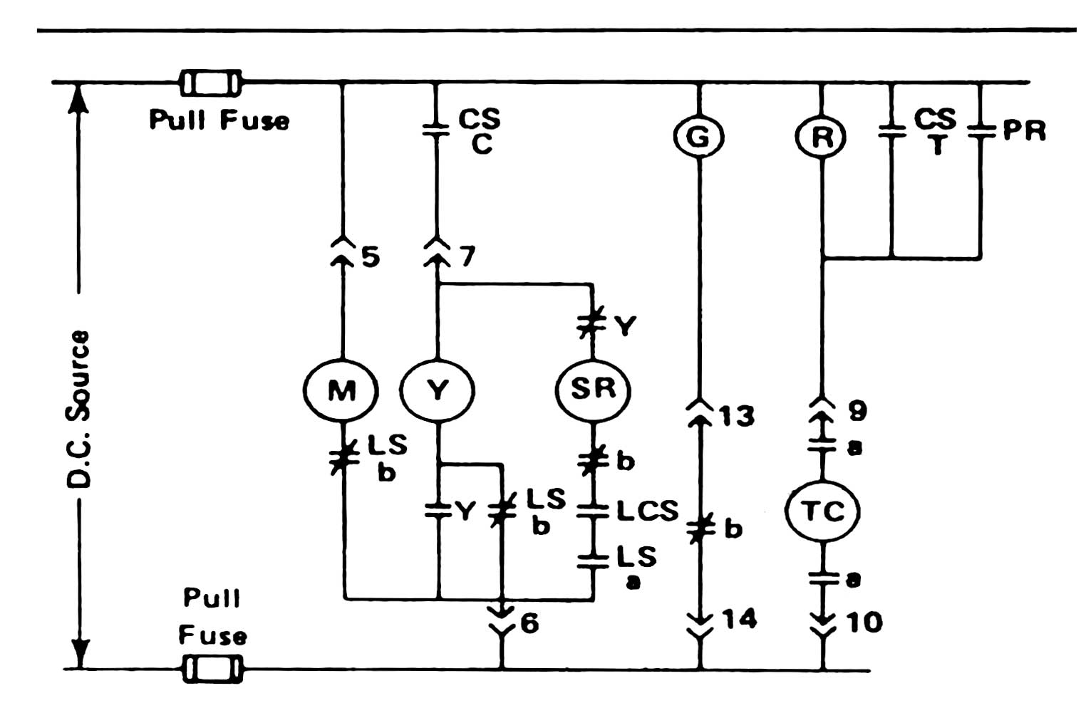
Circuit Breaker Control Schematic Explained

How To Wire A 110V Light Switch Fantastic Wiring 110V
Wiring Diagram Symbols Explained

New Motor Wiring Diagram Explained Motorcycle wiring

Schematic Diagram Stepper Motor Wiring schematic and

How to Wire a Starter (With Example Diagrams) In The


